-
e. Bulldozer trenches: The use of bulldozers to dig trenches for prospecting shallow placers is too common and too well known to need more than passing mention.
Because of its design, the bulldozer is more effective as a pusher than as a digger and for this reason it is best suited to ground less than 10 feet deep and to a working (pushing) distance not exceeding 200 feet. Two types of blade control are in general use; the blade may be raised and lowered hydraulically or it may be operated by a cable control. For digging prospect trenches the hydraulic blade is considered best as it provides a positive downward pressure; in fact, it allQws much of the tractor's weight to be put on the blade while digging hard ground. The cable-controlled blade has only its own weight to hold it down and as a result its cutting edge has a tendency to ride over any hard spots in the bottom of the trench.
The cost of bulldozer-dug trenches depends so much on the type and size of machine used and on the depth and hardness of the formation, and the operator's skill; any estimate of working speed or costs must be made on a case-by-case basis. Lorain (1944, pp. 1-8) has tabulated field data for trenching with bulldozers but his 1944 cost figures cannot be used without updating.
Possibly the greatest advantage to be gained in prospecting placers by means of bulldozer trenches, where applicable, is that they permit first-hand inspection of the ground. This makes it possible to visually determine the character and size of gravel to be dealt with and, in addition, the payor barren sections can sometimes be found by simple inspection and panning of the trench walls. Another feature is that a considerable area of bedrock can be exposed for inspection or testing as compared to pits or drill holes. In many cases, even where the ground is more than 10 feet deep, the results obtained from a few days of trenching with a bulldozer will provide the information needed to decide whether or not a more extensive (and expensive) sampling program is warranted.
-
f. Sampling with churn drills: Drilling is usually resorted to in deep or wet ground where sampling by means of pits, trenches or shafts is not practical. Many western gold placers, particularly those exploited by bucket-line dredges, have been sampled by churn drilling and it can be said generally that this method adapts well to the dredge operator's needs.
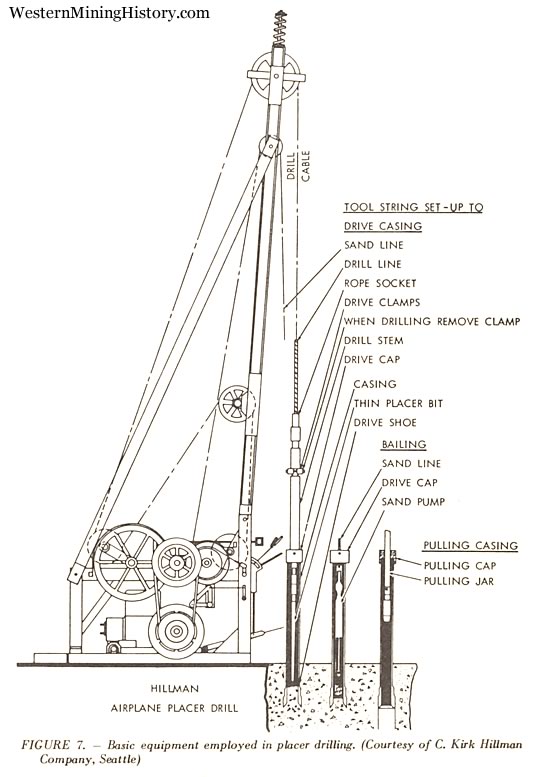
The basic drilling equipment consists of a heavy casing, a chisel-shaped bit suspended from a drill line and a vacuum-type sand pump. The overall operation can be divided into five steps as follows:
Driving.
Drilling.
Pumping.
Panning.
Pulling and moving.
The first step provides a measured core of gravel which serves as the sample. The gravel core is obtained by driving the casing (commonly referred to as the drive pipe) into the ground by striking it with a driving block attached to a heavy drill stem. The bottom end of the drive pipe is fitted with an alloy-steel shoe made with a sharp, beveled cutting edge. The effective diameter of this beveled edge determines the area of gravel or sample cut by the drive shoe as it is forced downward. A second step breaks up the core and prepares it for removal from the pipe. This is done by chopping the core with the drill bit which is repeatedly raised and dropped by means of a walking beam or crank acting on the drill line. Water is added during the drilling operation and when the material is reduced to a size that will permit pumping, the resultant sludge is removed from the hole with a special vacuum-lype sand pump. The cuttings are transferred to a measuring bucket which serves as a check to indicate if excess core is being removed or if extraneous material is running into the pipe.
The cuttings are washed in a rocker and the rocker concentrate further reduced by panning. The panner counts the gold colors recovered from each drive, estimates their weight and enters this information in the drill log. Examples of placer drill logs will be found in Appendix D.
The driving, drilling and pumping steps are successively repeated for each drive (usually 1 foot at a time) until the hole is completed. The engineer in charge then weighs the combined gold and calculates the value of the hole.
As a final step, the drive pipe is recovered by pulling. The drill is then moved to the next hole.

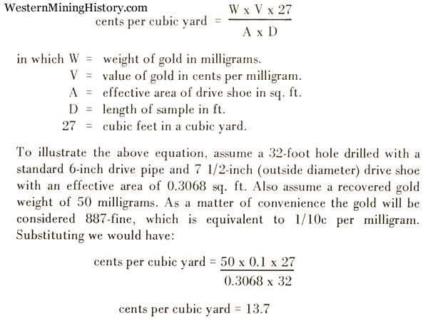
An illustrated. step-by-step description of the placer drilling process will be found in Appendix D, to which the reader is referred. The basic equipment is illustrated by Figure 7. As the pipe is driven downward it will, in theory, cut a cylinder of gravel having an area equal to that of the drive shoe and a length equal to the drive. A short length of core left in the bottom of the pipe to serve as a plug will, also in theory, prevent run-ins of extraneous material when pumping. Assuming ideal conditions and a perfect core, the value of the hole (or the sample increment) would be determined by use of the following equation:

It should be emphasized that drill hole values calculated in this manner would be correct only if all drives were perfect, that is, if the effective area of the drive shoe were exactly 0.3068 sq. ft., and if the correct length of core had entered the pipe with each drive. In the preceding example, the 50 milligrams of gold would have been obtained from a cylinder of gravel exactly 7 1/2 inches in diameter by 32 feet long.