Setting Up The Drill
The drill is placed in the desired location for the hole, leveled, and the derrick raised. One end of the sand line is attached to the vacuum sand pump; the other end is placed over the sand line sheave in the derrick and attached to the sand line drum. The drill line is placed over the crown sheave of the derrick, laced through the walking beam, and attached to the mainline drum, the cable socket being on the other end of the line.
For most placer operations, a string of tools usually consists of a rope socket, a stem, and a bit. When assembling a string of tools, lay the stem on the ground at the front of the drill; screw on the rope socket with the attached cable; then screw the bit on the lower end of the stem. A light wire brush and gasoline is recommended to clean the threads before assembling. A few drops of light oil are desirable on the threads.
Great care must be exercised in assembling a string of tools to see that the joints are tight. Screw the tool joints up by hand, then apply tool wrenches and set the joint up firmly by means of the chain wrench bar. Remember, most fishing jobs are due to improper setting of joints.
Many drillers use a stone in polishing the shoulder portion of the box and pin, before assembling. After a joint has been set up perfectly solid, a mark is sometimes made with a sharp cold chisel, half on the pin collar and half on the box. Each successive time this joint is screwed up, the mark on the box should go a little farther past the mark on the pin collar. By this method one can check and see that the joint is set up firmly. If, at the next fitting the joint does not go far enough, it is indicative that there is dirt on the face of the joint - or in the threads, which dirt must be removed.
After the stem and bit have been assembled, the tools are hoisted, the operator being careful not to kink the cable where it enters the socket. Check the frame to see that the tools hang directly above the center line of the drill and approximately 24 inches out from the front of the drill. You are now ready to start the hole.
Starting a Hole
At the site marked for drilling, a hole is dug approximately 16 inches deep. The gravel removed is examined to see whether it contains gold. A drive shoe is placed on one end of a length of drive pipe and a drive head on the other.
After carefully measuring the length of the pipe and shoe they are placed in the hole in a vertical position with the drive shoe on the bottom. Dirt is packed around the pipe to hold it in position. Where long lengths of casing are used, a well is usually dug directly in front of the drill. This is very difficult to do in wet ground.
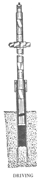
DRIVING THE PIPE
The tools are lowered, allowing the bit to enter the casing, the drive clamps are clamped on the square on the bit. It is important to see that the drive clamp bolts are kept tight. Loose nuts mean certain breaking of bolts.
The engine of the drill is started and operated at slow speed.
The drive clamps are lowered to within three inches of the drive head, the spudding lever is moved to the "On" position, and the casing gently tapped into the ground. The impact blow and feed are adjusted by gently raising the brake lever.
If the top soil is valueless, the pipe is driven to gravel. When the drive head reaches a point a few inches from the ground, it is removed and another length of pipe is carefully measured and coupled to the first length, care being taken to couple the pipe so that they butt in the center of the coupling. The drive head is then placed on the top of the next section of pipe and the operation resumed, core in the meantime is being removed as the pipe is driven deeper.
Whenever pipe is added, the threads are carefully cleaned and then greased with graphite and linseed oil and securely tightened by means of chain tongs. It is very important to grease the pipe and not the couplings. The portion of the thread one-quarter inch back from the end of the pipe is the part usually lubricated.
As soon as the hole has reached a depth sufficient for the bit and stem to enter the casing, the drive clamps are placed on the top square of the stem. After driving pipe to the desired depth, the drive clamps are removed.
Records are made of the depth of the drive pipe and also the cote. By starting at the bit and measuring back along the stem, the total length of pipe is marked with chalk or a piece of string on the line. The stem is lowered into the pipe and the distance between chalk mark and the top of the pipe represents the core remaining in the hole.
|
 |
|
|
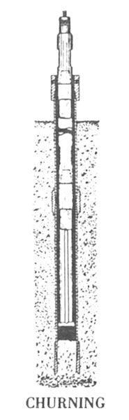
DRILLING PROCEDURE
Drilling process in the following manner: The driller measures and reports the length of core to the panner. This, and the depth of casing in the ground, are recorded in the log book.
Water is poured into the casing, the spudding lever thrown in the "On" position, and the core chopped up.
Some operators place a spoonful of lye in the drill hole when churning. Lye cuts any grease from the fine gold and prevents it floating away. There are times when there is a certain amount of vegetable oil in the ground or grease from pipe threads or wire line.
In placer testing it is always customary to try to drive the casing ahead of drilling. Three or four inches of core are always left in the casing to form a plug. This is contrasted with other types of drilling where the churning is done below the casing.
When large boulders are encountered, it is necessary to drill below the drive shoe; then the operator should check to see that the water level in the pipe is at least as high as the water plane in the ground, to prevent any values being carried into the casing.
When drilling through boulders greater speed can be obtained by using an ordinary rock bit or a four-wing type bit, than with a placer bit.
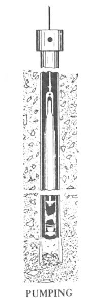
PUMPING OUT THE CORE
The tools are hoisted out of the pipe and held out of line of the drill casing by means of the tool guide. While the tools are being hoistered, a bucket-of water is usually poured on the rope and stem to wash off any values that might be clinging to the tools. The sand pump is raised by pulling on the sand pump lever. When the lever is released, a brake keeps the sand drum from turning, and holds the pump in position. When the sand pump lever is half way between the brake position and the hoist position, the drum is free, allowing the pump to fall freely to the bottom of the hole.
When the pump is at the bottom of the hole, the piston type plunger is at the bottom of the pump. By pulling on the sand drum lever, the plunger is rapidly raised, creating a strong vacuum, sucking in the gold, sand, mud, cuttings, etc. The efficiency of a sand pump depends on the speed with which the plunger is raised.
The foot valve in the bottom of the pump prevents material from escaping. Holding the sand drum lever out and keeping the sand drum engaged, brings the pump containing the core to the surface. Engineers very often drop several lead shot in the hole without the operator's knowledge, and then count them after the pumping to see that everything was removed.
It is common practice to pump before and after driving. In loose ground it is often possible to pump out the core immediately after driving. When the two pumpings are made before and after driving, they are caught in the same bucket and concentrated in one operation. The pumpings are ordinarily emptied into a mud box.
When prospecting a deposit having a deep overburden of valueless material, a one-inch rod is driven into the ground and as the pump is brought up, the foot valve of the sand pump is set on the rod, thus opening the valve and washing the contents out on the ground. The driller must be careful, however, not to throw away the contents when gravel is reached. Extreme care should be exercised so that the last three or four inches of the core is left in the bottom of the drive pipe to form a plug.
After the stem has been lowered into the pipe, and the depth of the remaining core checked and recorded in the log book, the tools are raised. The drive clamps are bolted on and the operations repeated. After the first drive, the clamps are bolted on the top square. It is impossible to do this at the start, as bit would strike the core when driving.
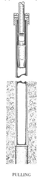
PIPE PULLING
A special feature of the Hillman Drills is their remarkable pipe pulling ability.
Using a top puller, the operation of pulling the pipe is as follows: The drive head is removed from the top of the casing. The knocking head is slipped over the pipe pulling jar. The rope socket is attached to the pin of the pipe pulling jar. Some operators prefer to use the rope socket and stem above the pipe pulling jar but a sharper blow seems to be obtained when it is below. The knocking head is screwed on the top of the pipe in place of the driving head. The drill is placed in the spudding position and the string of tools is raised far enough so that by means of the spudding action they are thrown at the driving head. A sharp blow is obtained rather than a straight pull. This is exactly the reverse action of pipe driving, the blow being directed at the lower face of the knocking head instead of the top of the driving head.
Sometimes considerable time is saved by using a hand hoist in conjunction with the bumping action. By thus having a tension on the line, the pipe does not have a chance to drop back after each blow and a continuous upward tension on the pipe is maintained.
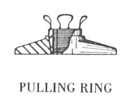
In extreme instances where the burden of jarring the pipe is too great for normal blow delivered and the upward tension of a hand hoist line is insufficient, a pipe pulling ring should be used. By placing the ring on the casing-head and hand jacks beneath the flange on the ring, a tremendous upward pressure is added to the jarring effect of the stem which starts the pipe upward.
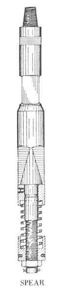
PIPE PULLING WITH CASING SPEAR
The C. Kirk Hillman Company makes a three-jaw casing spear. Three jaws are used to eliminate distortion of the pipe as is usually the case when two jaws are used. Four jaws do not work as well as three jaws for six-inch casing and smaller, for not enough stock is then left in the center of the spear to withstand the constant hammering.
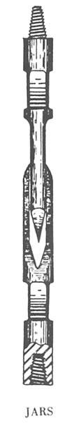
The operation of pulling the pipe by means of the spear is as follows: The string of tools is assembled, consisting of a rope socket, a stem, a set of long stroke jars and the trip casing spear. The jaws of the spear are set by using the spider furnished with the spear for pulling back the jaws and compressing the spring. The anvil block directly on top of the spring has a key which slides into a notch on the lower end of the spear; this key is pressed in. The spider is then removed. The string of tools is then lowered into the casing. Pulling is usually done from the last length. When the spear is in the last length of pipe it is hoisted up, sinking the jaws into the casing. The drill is placed in the spudding position and the string of casing jarred upwards. To release the casing, the spear is struck a sharp blow from the top. This causes the anvil block to strike the top of the jaws, which releases the spear. The tools are then hoisted out of the casing. The lengths of casing out of the ground are uncoupled and the operation repeated.
|
 |
TREATMENT OF THE CORE
When the sand pump is hoisted out of the casing, the helper, or panner, grasps the lower end of the pump, walks'back from the drill, and lays the lower end on the saddle of the dump (or mud) box. The bail end of the sand pump is then lowered into the bottom of the dump (or mud) box. When the pump in this position the foot valve is approximately on an even height with the panner's eye. While the pump is in this jackknifed position, it is thoroughly washed both inside and out. A dipper, formed by fastening a handle on a gallon tin can, is used for pouring water in the foot valve and slushing out the material. The pump is hoisted and jackknifed in the other position. The lower end of the pump on the previous washing is now the top. The second washing is not always essential, but is advisable, especially when working in rich ground. Directly below the lower end of the mud box is located a tub containing the volume bucket.
MUD BOX OR DUMP BOX
The legs and sides of the dump box are made of surfaced fir, two inches by four inches. The trough is formed of 16-gauge steel. The top end of the box is welded solid. The lower end is also welded and fitted with an adjustable gate which can be set to control the flow into the volume bucket and avoid splashing.
THE VOLUME BUCKET
The Volume Bucket, holding one cubic foot, is 13.5 inches in 13 diameter and 12 inches in height. The measuring stick is I calibrated in tenths and hundredths of a cubic foot. A good practice is to measure the total quantity of material pumped I from each hold and to compare the results from all holes drilled in similar material. A fair average can be obtained and used as a check on each separate property. Some operators calculate twenty cubic feet of material so measured to represent one cubic yard actually drilled.
The volume bucket measurement entails complete disintegration of the material and its reaggregation before measurement takes place. The escaping slimes may or may not fill the interstices of the sand with doubtful increase of the volume of the sand. Therefore, measurements made by this method will not always check with the theoretical volume or the volume as measured by the rise of the core in the pipe.
The material in the volume bucket is thoroughly stirred to break up any sticky lumps and then the water is poured off. Records are made in the log book of the measured volume of the core Directly beside the volume bucket is the panning table.